
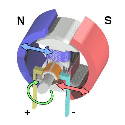
Brushed DC motors are fundamental electromechanical devices that convert electrical energy into mechanical rotation through the interaction of magnetic fields. These motors consist of a stationary field magnet (stator) and a rotating armature (rotor) with wire windings. The brushes and commutator enable current to flow through the armature windings, generating electromagnetic forces that cause rotation. Thanks to their simplicity, reliability, low cost, and ease of control, brushed DC motors are widely used in various low-power applications.
The torque constant (Kₜ) is a key parameter in DC motor performance. It defines the relationship between armature current and output torque and is expressed in newton-meters per ampere (Nm/A). This constant determines how effectively a motor converts electrical current into mechanical torque. Engineers use the torque constant for motor selection, performance modeling, and control system design. A motor with a higher torque constant delivers more torque per unit of current, often suggesting higher efficiency—though typically with trade-offs in other performance aspects.
At the core of DC motor operation is the Lorentz force, which describes the force experienced by a charged particle moving through an electromagnetic field. In motor applications, this principle explains how current-carrying conductors in the armature experience forces when placed in the stator’s magnetic field. The Lorentz force is given by:
F = q(E + v × B)
where:
q is the charge,
E is the electric field,
v is the velocity of the charge, and
B is the magnetic field.
For motor analysis, we use a more practical form of this equation that applies directly to conductors. When current flows through a wire in a magnetic field, it experiences a force perpendicular to both the current direction and the magnetic field. Since the wire length vector dL aligns with the current direction, current can be treated as a scalar, giving us:
dF = I · dL × B
where:
I is the current,
dL is the differential length vector of the wire, and
B is the magnetic flux density vector.
This cross product results in a force vector perpendicular to both the wire and magnetic field, following the right-hand rule.
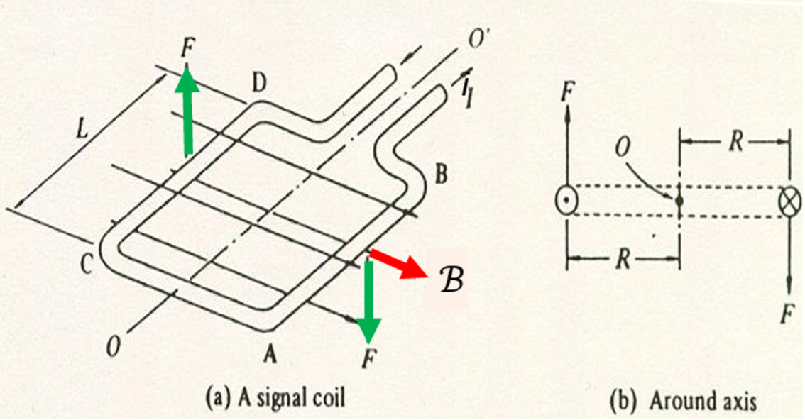
To derive the torque constant from the Lorentz force, we can analyze a simplified model: a single coil in a uniform magnetic field. When current flows through the coil, each straight segment experiences a force that is perpendicular to both the current and the field. If the coil has radius R, the torque from a single turn is:
τ_coil = 2 · F · R = 2 · I · L · B · R
For a coil with N turns, the total torque is:
Tₘ = 2 · I · L · B · R · N
From this, we define the torque constant as:
Kₜ = 2 · L · B · R · N
Measured in newton-meters per ampere (Nm/A), this gives us the fundamental relationship for DC motors:
Tₘ = Kₜ · I
This simple yet powerful equation shows that torque output is directly proportional to armature current, with Kₜ serving as the proportionality constant. Looking to optimize your next motion system or choose the right brushed DC motor? Contact Quadrant today to speak with our engineering team and explore how our custom solutions can power your innovation.